One of the most frequent hurdles when building DIY electronics projects is dealing with unmatched voltages. You might have a 12V DC power supply or a 9V battery, but the component you want to power—such as an LED indicator, an optical sensor, or a small module—only requires 3.3V or 5V. Connecting the higher voltage supply directly to that delicate part will cause excessive current to rush through, instantly destroying it.
The quickest, most affordable, and most accessible component to step down that voltage is a resistor.
In this comprehensive guide, you will learn the fundamental physics of voltage dropping, step-by-step mathematical calculations, how to calculate power dissipation so components do not burn out, and how to verify your physical parts accurately.
1. The Core Principle: How a Resistor Drops Voltage
A resistor does not act like a sponge that magically soaks up voltage. Instead, voltage drop occurs strictly when electric current flows through a resistive material. This behavior is defined by Ohm’s Law:
Voltage Drop (V)=Current (I)×Resistance (R)
Where:
- VVV (Volts): The potential difference dropped across the resistor terminals.
- III (Amperes): The current flowing through the circuit loop.
- RRR (Ohms, Ω\OmegaΩ): The resistance of the component.
When electrical charges push through the resistor’s internal resistance, some of their electrical potential energy is converted into heat. This creates a predictable difference in voltage between the input and output sides.
Important rule: If no current is actively flowing through the circuit (I=0), the voltage drop across the resistor is zero. The full input voltage will pass straight through to the other side until a complete circuit is established.
2. Step-by-Step Calculation: Sizing a Series Dropping Resistor
When you are powering a constant-current device (such as an LED), placing a single resistor in series with the load is the standard method.

To calculate the exact resistance you need, follow these three steps:
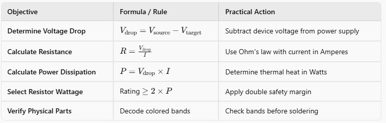
Step 1: Calculate the Voltage to Drop (VdropV_{\text{drop}}Vdrop)
Subtract the operating voltage of your device (Vtarget) from your power supply voltage (Vsource):
Vdrop=Vsource−Vtarget
Step 2: Determine Operating Current (III)
| Look at the component’s datasheet to check how much continuous current it draws. Always convert milliamperes (mA) into amperes (A): I=1000Current in mA (For example, 20 mA=0.02 A20\text{ mA} = 0.02\text{ A}20 mA=0.02 A). |
Step 3: Compute the Resistance (RRR)
| Divide the voltage you need to drop by the operating current: R=IVdrop If you want to skip manual formula calculations or instantly cross-verify your Voltage (V), Current (I), Resistance (R), and Power (P), you can use this online Ohms Law Calculator to get instant, error-free results. |
3. Practical Example: Powering an LED from 12V
| Let’s look at a typical workshop scenario: You want to run a standard red LED from a 12V car battery or adapter without burning it out. Source Voltage (Vsource): 12V LED Forward Voltage (Vtarget): 2.0V Safe Operating Current (𝐈 ): 20 mA= 0.02 A |
The Math:

Because 500Ω is not an everyday standard commercial value in the E24 series, you should round up to the nearest standard resistor value, which is 510 Ω510\,\Omega510Ω or 560 Ω560\,\Omega560Ω. Rounding up slightly reduces current, keeping the LED cool and dramatically extending its operational lifespan.
4. Calculating Resistor Wattage & Preventing Overheating
A common mistake made by makers is calculating the Ohm value correctly but picking a resistor with an insufficient wattage rating.
When a resistor drops voltage, that electrical potential transforms into thermal heat. If the resistor cannot dissipate that heat into the surrounding air fast enough, it will smoke, crack, and fail.
Calculate heat dissipation using the electrical power formula:

Using our LED example: P=10V×0.02A=0.2 Watts
Most small hobby through-hole resistors are rated for 0.25W (1/4 watt). While 0.2W is technically within the 0.25W limit, running a component at 80% capacity makes it uncomfortably hot to the touch.

5. Identifying Physical Resistors Before Assembly
Once you know the exact resistance required—such as 510Ω, 1 kΩ, or 4.7 kΩ—the next practical step is locating that physical resistor in your parts organizer.
Unlike microchips or modules, standard through-hole resistors do not display numerical values. Instead, they use printed color bands (4, 5, or 6 bands) to represent resistance value, multiplier, and manufacturing tolerance. Under dim workbench lighting, brown, red, and orange bands can look confusingly similar.
To avoid putting the wrong value into your circuit, you can verify your component’s color bands using this free resistor calculator. Decoding 4-band, 5-band, and 6-band resistors takes just seconds and ensures your physical parts match your theoretical math before soldering.
6. Critical Limitations: When NOT to Use a Dropping Resistor
While dropping voltage with a series resistor is quick and convenient, it is not suitable for every circuit:
- Fluctuating Loads (Microcontrollers & Motors): If the current draw (I) of your load changes, the voltage drop will fluctuate with it. When a microcontroller enters low-power sleep mode, its current draw plunges. This causes the resistor’s voltage drop to collapse, sending the full input voltage directly into your sensitive chip.
- High Current Waste: If you try dropping 12V down to 5V for a device requiring 1A of current: P=(12V−5V)×1A=7 Watts You would waste 7 Watts of energy purely as heat, draining batteries rapidly and requiring a bulky heat sink.
7. What Should You Use Instead?
When a simple resistor is not suitable, use one of these dedicated voltage regulation methods:
- Linear Regulators (e.g., LM7805, AMS1117): Provides a rock-solid, constant DC output voltage regardless of fluctuating current, ideal for sensitive logic boards.
- Switching DC-DC Buck Converters: Converts high voltages down to lower voltages with 85% to 95% energy efficiency. Perfect for high-current loads or battery-operated electronics.
Summary Reference Table